Drinking Water Protection
- Drinking Water Protection Home
- About Us
- A-Z Index of Contaminants in Water
- Community Public Water Supply
- Drinking Water Grants and Loans
- Drinking Water Institute
- Drinking Water in Schools and Child Cares
- Drinking Water Revolving Fund
- Laws and Rules
- Noncommunity Public Water Supply
- Source Water Protection
- Water Operator and Certification Training
- Drinking Water Protection Contacts
Related Topics
- Annual Reports
- Drinking Water Risk Communication Toolkit
- Drinking Water Protection External Resources
- Fact Sheets
- Forms
- Invisible Heroes Videos: Minnesota's Drinking Water Providers
- Noncom Notes Newsletter
- Sample Collection Procedures (videos, pictures, written instructions)
- Waterline Newsletter
Related Sites
- 10 States Standards
- Clean Water Fund
- Health Risk Assessment – Guidance Values and Standards for Water
- Minnesota Well Index
- Water and Health
- Wells and Borings
Environmental Health Division
Dying for a Drink?
The search for water at Lakewood Cemetery has a history as rich as its occupants.
From the Fall 1999 Waterline
Quarterly Newsletter of the Minnesota Department of Health Public Water Supply Unit, Waterline
A complete list of feature stories can be found on the Waterline webpage.
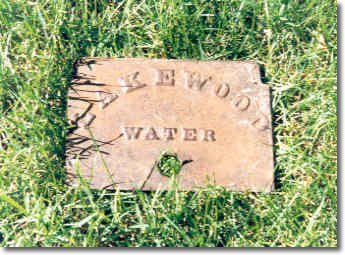 The city of Minneapolis has approximately 364,000 residents; however, this number does not include the permanent residents of a notable necropolis tucked between Lakes Calhoun and Harriet. Covering approximately 250 acres, Lakewood Cemetery is the interment site of 130,000 people. A stroll through its scenic grounds reveals a who’s who of civic pioneers with familiar names such as Pillsbury, Washburn, and Lowry adorning the often-ostentatious grave markers and expansive mausoleums.
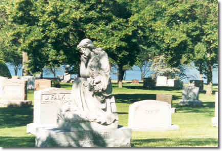
Although it’s debatable as to whether these people are in continuing need of water, it is clear that the grounds require a plentiful supply to keep the peaceful green of the grass and the shade of the trees. This was true even when the cemetery covered barely half its current territory and held a far smaller population.
As far back as the 1880s, when the cemetery was 10 years old, the search for water was on. It was believed that an artesian well was on the property, prompting the cemetery association to spend nearly $12,000 to drill 2,150 feet into the ground (still the record for the deepest water well in Hennepin County). Unfortunately, at the time this well was sunk, deep well pumps for insertion in the casing were not yet available, leaving no means for bringing the water to the surface.
However, Bruce Olsen, head of the Minnesota Department of Health’s Source Water Protection Unit, said the drilling of the deep well at Lakewood Cemetery yielded another valuable resource—information about geologic formations in the Twin Cities that Olsen claims “is as useful today as it was then.” Calling the well a “major geological test hole for its time,” Olsen adds, “It is indicative of the bedrock formations in the metro area. It opens up all the rock formations that yield water in the metro area.”
Drilled in the middle of the geologic structure known as the Twin Cities Basin, the 2,150-foot-deep well first encounters bedrock in St. Peter sandstone at a depth of 256 feet and then hits the Prairie duChien-Jordan aquifer at 318 feet. Below that is the Franconia-Ironton-Galesville aquifer and then the Mount Simon-Hinckley aquifer, which ends at 1,123 feet, although the drilling continued for another 1,000 feet into non-aquifer material. The drills reached basalt at a depth of 2,135 feet and penetrated 15 more feet into it.
Olsen says the well encounters “a real mix of water. Water from the Prairie duChien-Jordan aquifer is decades old [from the time of infiltration]. Water from the Mount Simon-Hinckley is tens of thousands of years old.”
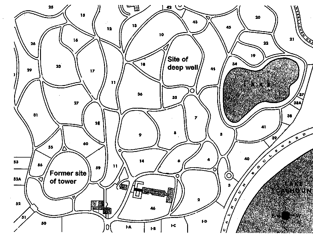
Lakewood next looked to a neighbor with a plentiful source—Lake Calhoun—and began pumping water from the lake into a tower it built near the southeast corner of the cemetery. The site of the tower was on the highest spot of Hennepin County, making it an easy matter to feed the grounds by gravity. The tower was eventually dismantled and the hill itself reduced in height as a means of providing fill for other spots in the cemetery. This area is still undeveloped, and visitors can easily spot the site, flanked by Sections 55, 60, and 59.
In 1913, protests developed over the amount of water the cemetery was drawing from Lake Calhoun, reported to be in excess of 300,000 gallons a day. Minneapolis Park Board commissioners claimed that the cemetery’s actions threatened to lower water levels in the city’s lakes and rob “Minnehaha Falls of a goodly portion of its water supply.”
Thereafter, Lakewood supplied its water needs from within its boundaries. Toward that end, it created its own eight-acre lake from a swamp that had occupied 15 acres between two sections of the cemetery. The operation involved draining the swamp water into Lake Harriet while dredging 177,000 cubic yards of sand and gravel from Lake Calhoun to fill seven acres of the swamp. The cemetery donated a section of land to the Park Board in exchange for the permission to use the adjacent lakes for draining and dredging.
The lake became the cemetery’s main source of water as it flowed by gravity through a 24-inch diameter conduit to a wet well located in a pump house at the north end of Section 44, close to the site of the 2,150-foot-deep well. A centrifugal pump then sent the water to the 9,000-gallon hilltop tower, traveling approximately one-third of a mile through six- and eight-inch diameter cast-iron mains with various distribution taps along the way. In addition to serving as a storage facility for periods of high demand, the hilltop tower also maintained pressure in the mains for low-demand needs such as hose and vase watering.
The lake supply was supplemented in 1936 by a 500 gallon per minute (gpm) well pump in the basement of the administration building that discharged water directly into a 3,000-gallon open surge tank, also located in the basement of the building. A 300-gpm booster pump subsequently pumped water from the surge tank to the hilltop tower to satisfy the tower’s needs during periods of low demand.
The 1949 study also recommended that a 8-inch water main be constructed from the lake pump to the office area and subsequently be connected to a major distribution system being proposed for the redevelopment of the northeast corner. The larger watermain would substantially improve watering pressure within that major distribution system. The study also recommended that a 6 inch watermain be looped through the southerly portion of the cemetery to improve the operating pressures also existing in that area. The proposed 8 inch water main was installed in 1950, however, the 6-inch watermain recommended for installation in the southerly portion of the cemetery was apparently never installed.
In 1953, based on a study begun four years earlier, a 3,200-gallon hydropneumatic tank was installed underground immediately north of the administration building. The tank was piped into the water distribution system, which received water directly from the 300-gallon booster pump and discharged water into the cemetery mains. An autocon control system was also installed to operate in concert with the hydropneumatic tank, starting and stopping the 300-gpm pump upon demand. The basic elements of the water supply system was then the lake pump, the 500-gpm well pump, the surge tank, the 300-gpm booster pump, the 3,200-gallon hydro-pneumatic tank and the autocon control system, obviating the need for the water tower and bringing about its demise, along with much of the hill it topped.
This operation only satisfied the low demands of the cemetery for hand watering, vase watering and low level lawn sprinkling. During the summer months when periods of high sprinkling demand existed, the lake pump was called into operation and pumped directly into the water distribution mains. The lake pump was activated or started manually or through a combination of manual and time-clock equipment and functioned completely independently of the 3,200-gallon hydropneumatic tank and its control system.
Continuing problems from the lake pumping operation, caused by fluctuating lake levels and the plugging of sprinkler nozzles from contaminated lake water, brought about the construction of Water Well No. 3 in 1957, to the south of the administration building. The following year, a 15-horsepower, 130-gpm submersible pump was installed in the well, and a small water line was constructed from the pump discharge to a nearby storm sewer. The storm sewer subsequently discharged into the lake, allowing a continuous flow of water from the pump to the lake and a constant water level within the lake. To overcome the plugged nozzle problem, sediment separators were installed at various locations along the major watermains in an effort to intercept lake water contamination.
In 1969, a 125-horsepower, 1,150-gpm pump was installed in Well No. 3 replacing the 15-horsepower submersible pump. The new pump was piped to discharge directly into the cemetery distribution system rather than into the lake, virtually eliminating use of the lake pump and the contaminated lake water within the system. This same year a new power supply was installed from 36th Street to the office building pumping panel. A new autocon control panel was also installed in 1969 to operate Well Pump No. 1, the booster pump from surge tank to pressure tank, and Well Pump No. 3. The autocon controls allowed the supplied system to operate automatically, its only limits being the capacity of the pumps.
Today the cemetery’s wells supply the needs of the grounds and all buildings on the site except for the administration building, which is connected to the Minneapolis water supply.
Go to > top.